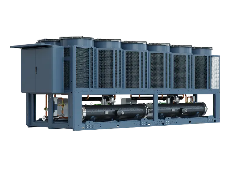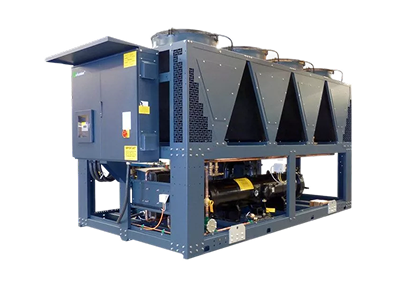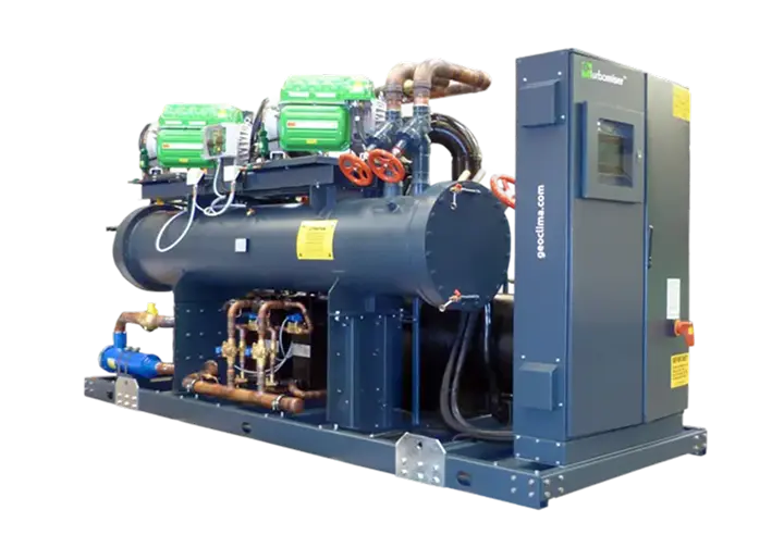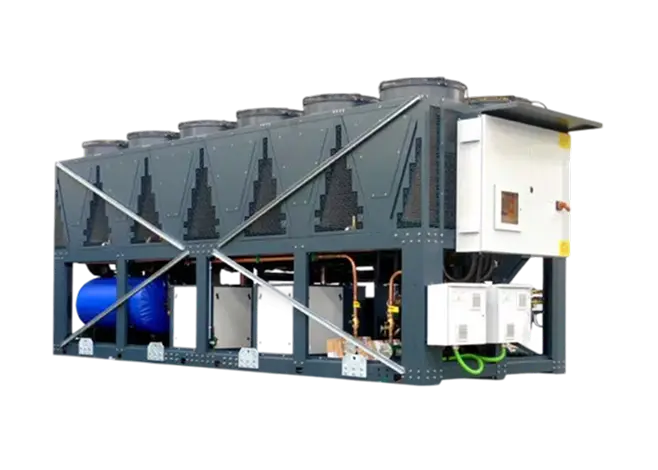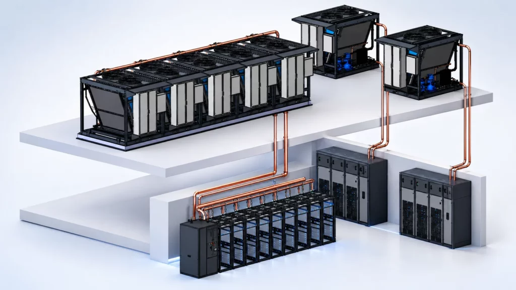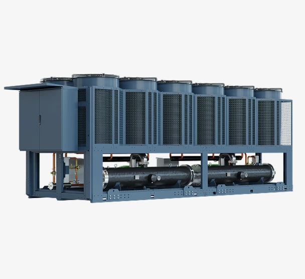

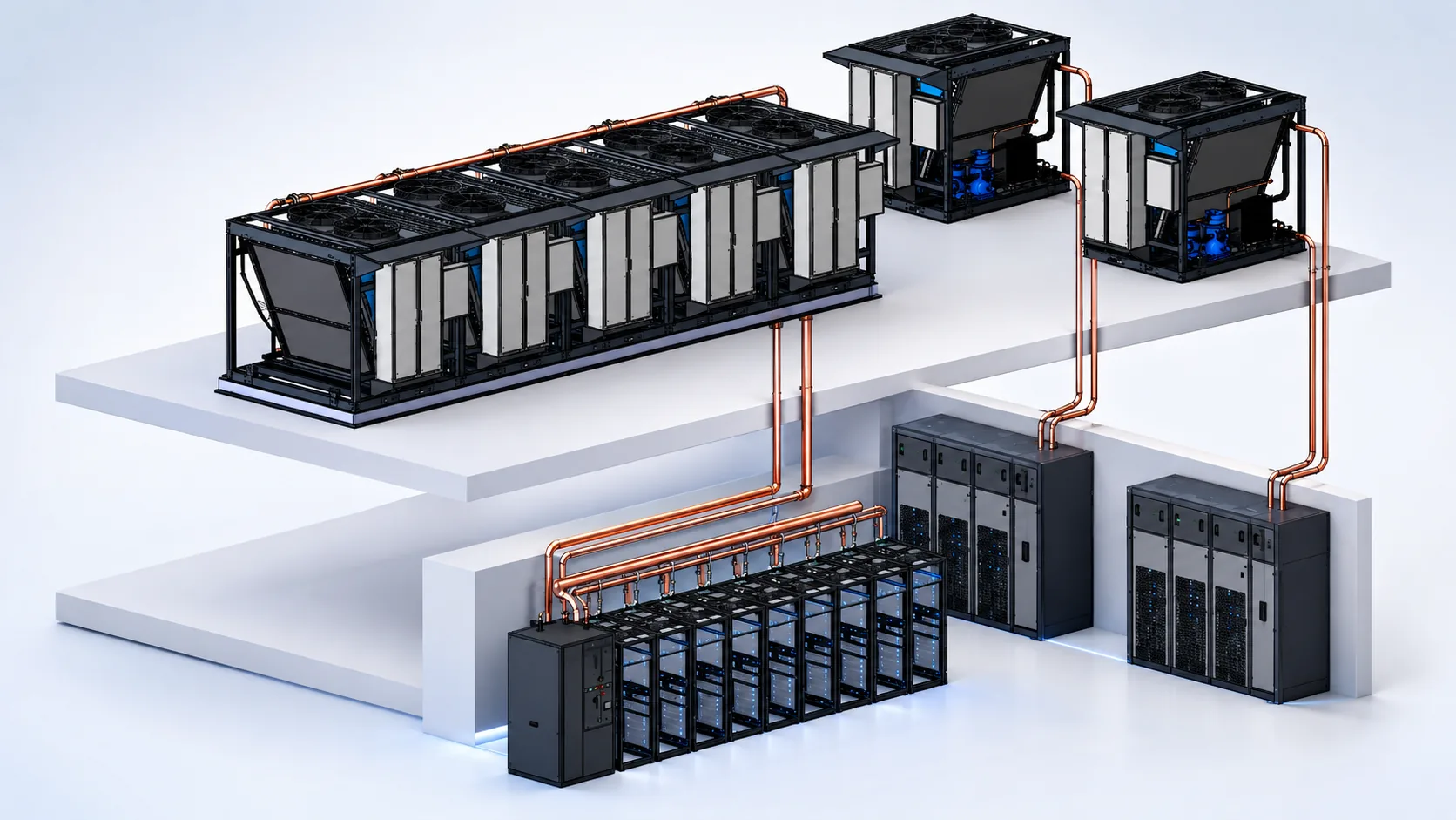
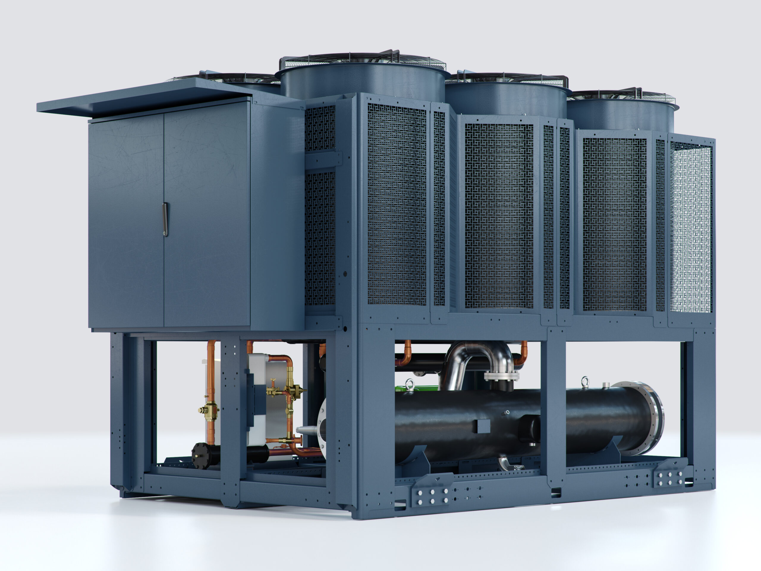
When it comes to optimal chiller design, the objective is clear: maximise capacity and efficiency while minimising footprint. Achieving the highest performance within the smallest possible space has become a defining goal for modern chilled water systems.
Over the past two decades, the industry has seen significant advances in compressor technology. Innovations such as oil-free magnetic bearing compressors (e.g. Turbocor®) and the evolution of screw compressors with variable speed inverter drives have delivered substantial gains in efficiency and operational performance.
However, one fundamentally important – yet often underutilised – area for improvement is condenser heat rejection surface area. Optimising this element can unlock meaningful benefits across multiple dimensions, including increased cooling density, improved electrical efficiency, and reduced noise levels. In many cases, enhancements to condenser performance can deliver gains comparable to those achieved through more complex mechanical innovations.
Back to Basics
Increasing condenser surface area provides three primary thermodynamic advantages:
Improved heat rejection and lower condensing temperature: A larger heat transfer surface allows more effective rejection of heat to ambient air. This reduces the required condensing temperature (and therefore pressure) for a given load.
Reduced compressor power consumption: Lower condensing pressure reduces the compression ratio. This directly decreases the work required by the compressor to circulate refrigerant and meet the cooling demand, improving overall system efficiency (kW/ton or EER).
Lower condenser air-off temperature: With a larger surface area and lower condensing temperature, the temperature rise across the air-side heat exchanger is reduced. This results in lower discharge (air-off) temperatures, which mitigates the risk and impact of air recirculation—an important consideration in real installations.
Practical Constraints
If increasing condenser size delivers such clear benefits, why is it not universally adopted?
The answer lies in two primary constraints: space and cost. Larger condensers require more physical footprint and increased material content, both of which drive up installation constraints and capital cost.
With traditional copper–aluminium finned heat exchangers, increasing surface area is typically achieved by:
- Increasing coil depth
- Adding more tube rows (passes)
- Expanding face area
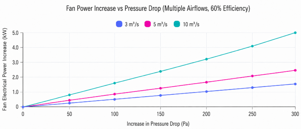
However, increasing coil depth introduces a significant drawback. As the coil becomes thicker, air-side pressure drop increases, requiring higher fan static pressure to maintain airflow. This leads to:
- Increased fan energy consumption
- Higher noise levels
- Diminishing returns on overall efficiency
As a result, there is an inherent design trade-off between maximising heat transfer area and maintaining acceptable airflow resistance, acoustics, and system footprint.
Condenser Coil Evolution
For much of the 20th century, copper tube-and-fin air-side heat exchangers were the dominant technology for heat rejection. These designs relied on copper tubes to carry the refrigerant, with aluminium or copper fins attached to increase the effective surface area for heat transfer.
In the 1970s and 1980s, the automotive industry began pioneering a more compact and efficient alternative: the aluminium microchannel heat exchanger. This design uses flat aluminium tubes containing multiple small internal passages (microchannels) through which the refrigerant flows.
These flat tubes are arranged in parallel and connected by thin, louvred aluminium fins. The fins are carefully angled to disrupt the aerodynamic boundary layer as air passes through the coil, significantly enhancing heat transfer performance. This combination of increased surface area, improved airflow characteristics, and reduced material thickness led to higher efficiency and a more lightweight, compact design compared to traditional tube-and-fin constructions.
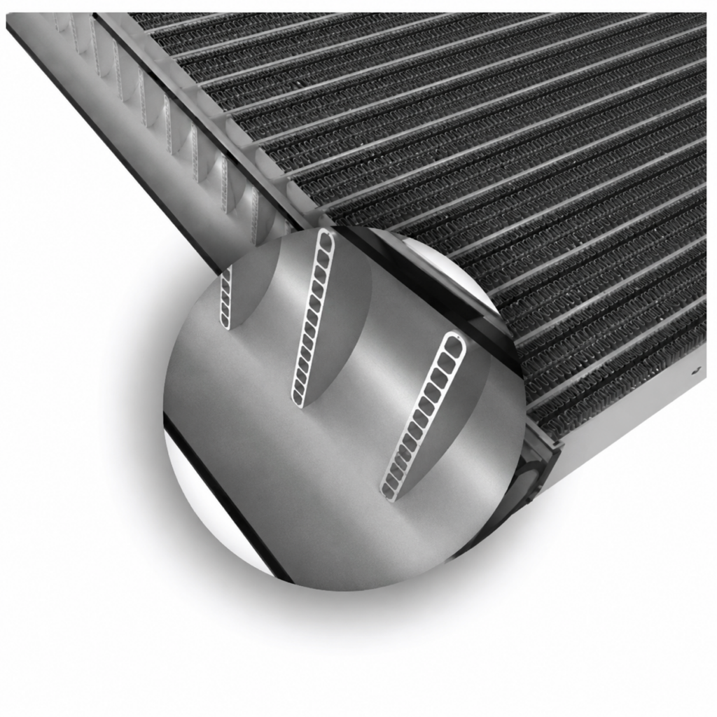
Over time, this technology transitioned into the HVAC industry as improvements in manufacturing techniques allowed microchannel coils to be produced in larger formats, making them practical and economically viable for broader heat rejection applications.
Microchannel condensers and free-cooling water/glycol coils are now widely adopted by premium chiller manufacturers, offering up to 40% greater heat transfer per square metre compared with traditional copper tube-and-fin technology.
The air-side pressure drop across a microchannel coil is also significantly lower, typically reduced by 30–40%. This improvement is driven by lower aerodynamic drag, reduced wake formation downstream of the coil face, and a substantially shallower coil depth.
As a result, airflow distribution across the coil is more uniform, enhancing thermal performance. In addition, the reduced pressure drop allows for lower fan power requirements to achieve the same airflow, improving overall system efficiency and reducing operating costs.
The next step
It is therefore clear that microchannel coil technology already delivers significant benefits for chiller condenser design. But can this technology be advanced further to meet the industry’s ongoing demand for higher capacity, improved efficiency, and reduced footprint?
At Munters, we have taken the next logical step in this evolution. By further optimising the design, we have increased the effective condenser surface area by an additional 45% or more – without increasing the chiller’s original footprint.
Round peg – Round hole. – Circlemiser®
Condenser coils are typically arranged within a chiller’s chassis in V or W configurations along their length.
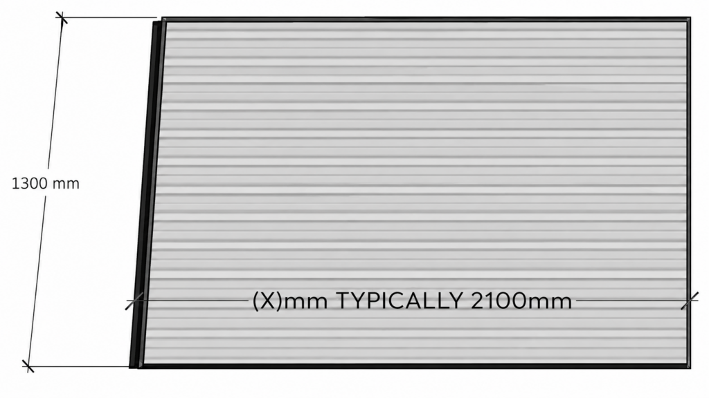
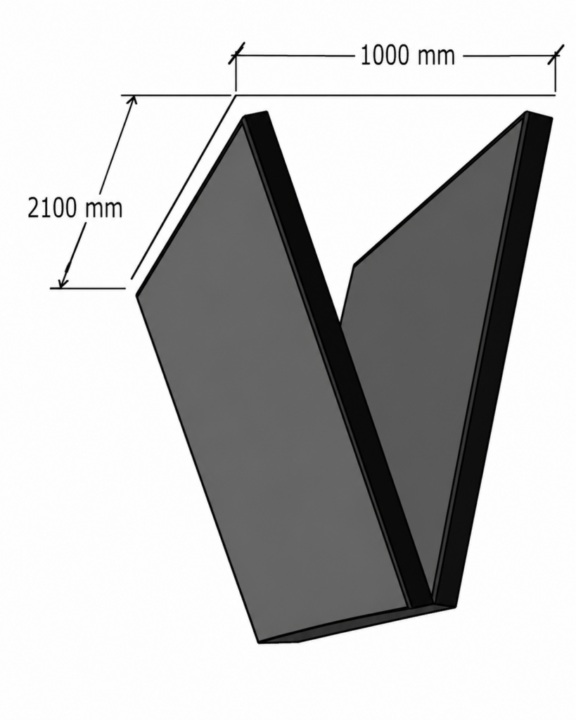
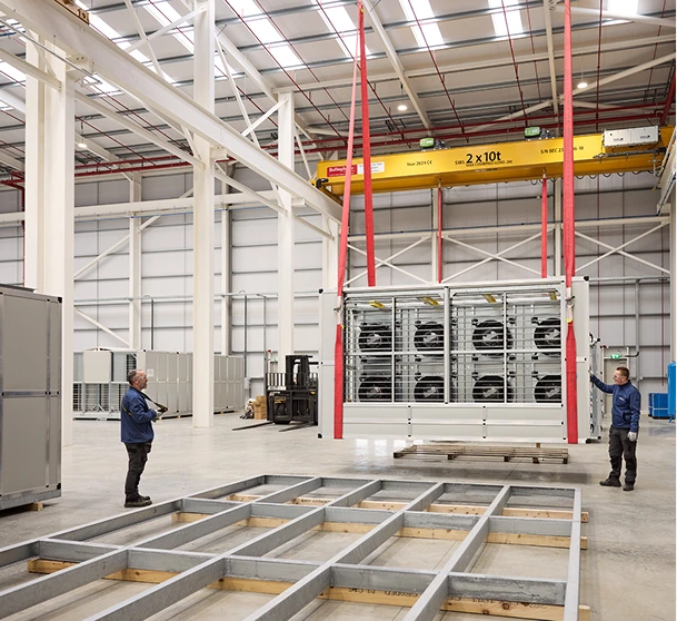
This constraint limits individual coil dimensions to approximately 2100 mm × 1300 mm, ensuring the overall chiller frame remains suitable for standard road transport.
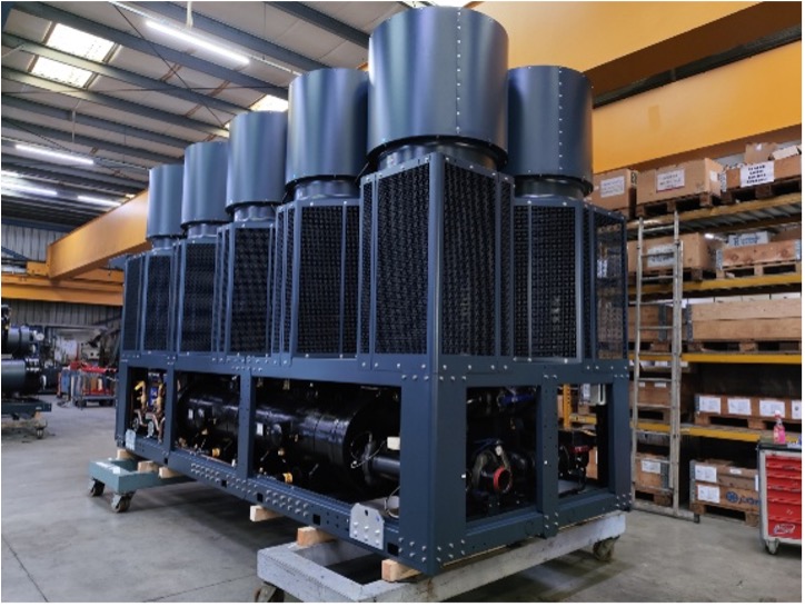
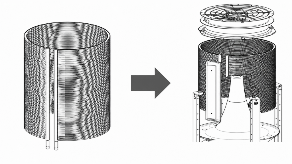
However, with Munters Circlemiser chiller, microchannel coil technology offers greater design flexibility. Unlike traditional geometries, these coils can be formed into a circular arrangement, enabling a substantially longer effective coil length to be integrated within the same footprint.
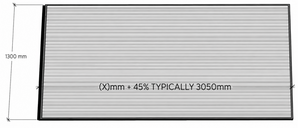
This approach enables two 3050 mm long coils to be installed within the same space that would traditionally accommodate two 2100 mm coils in a conventional ‘V’ coil arrangement.
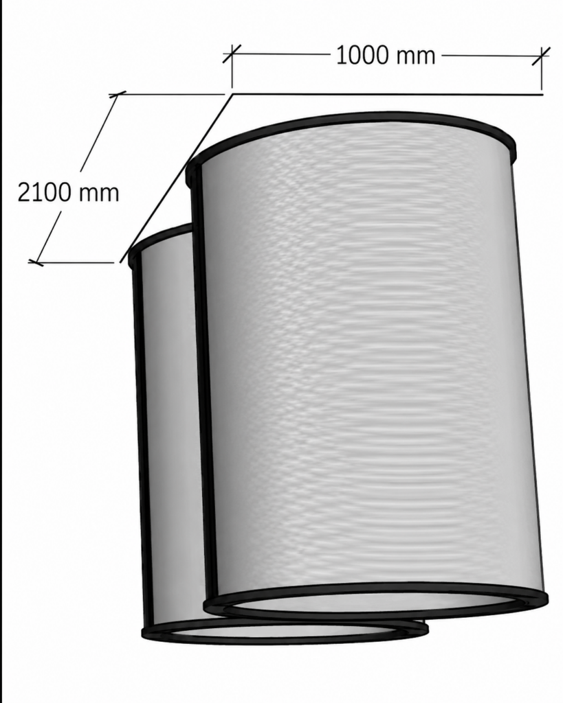
This coil geometry offers further advantages. As fans are inherently circular, integrating them with a condenser coil configured as a cylinder of matching diameter enables near-uniform airflow across the entire coil surface area.
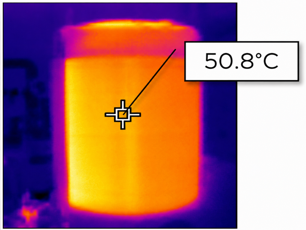
Uniform airflow, combined with the increased surface area, leads to improved coil utilisation and lower leaving air temperatures. This, in turn, helps to mitigate air recirculation issues commonly experienced on sites operating air-cooled chillers.
This thermal image clearly demonstrates the uniform surface temperature achieved across the coil, highlighting the effectiveness of this design approach.
CIRCLEMISER delivers a significant advancement in vapour compression cycle performance
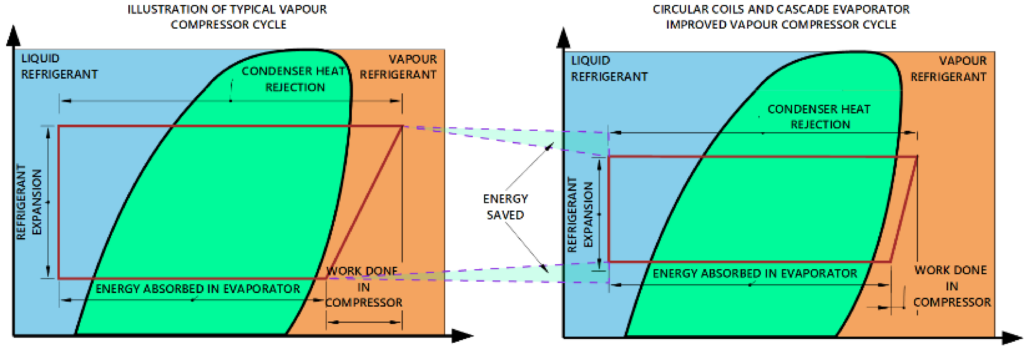
The substantial increase in condenser surface area reduces the pressure lift required by the compressor across all operating conditions. This reduction in lift directly translates into electrical energy savings of approximately 35%.
The diagram below compares a conventional vapour compression cycle with that of an enhanced system incorporating increased condenser surface area. Two distinct areas of energy improvement are evident: the first resulting from a reduction in condensing temperature, and the second from an increase in evaporating temperature.
This additional efficiency gain is achieved through the implementation of Munters cascade evaporator arrangement, which raises the average suction temperature. The principles and science behind this innovation will be explored in a separate document.
In conclusion, the simple yet highly innovative approach adopted in the Munters CIRCLEMISER chiller range delivers real-world energy savings of over 35% compared to the traditional technologies it replaces.

Want to explore these cooling topics with your team?
Our CIBSE-approved Data Center Cooling CPD gives consultants and engineers the opportunity to discuss cooling principles, trade-offs and project-relevant questions directly with Munters specialists. Explore the CPD →