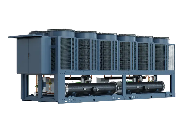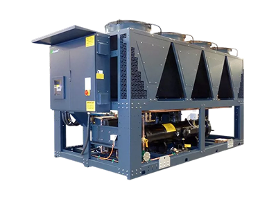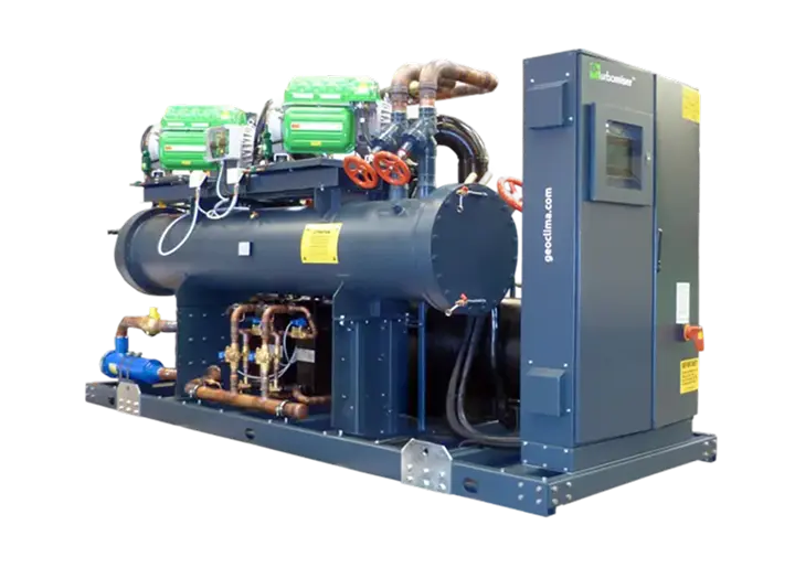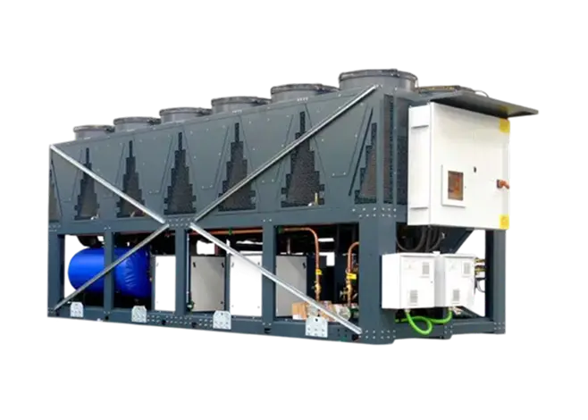

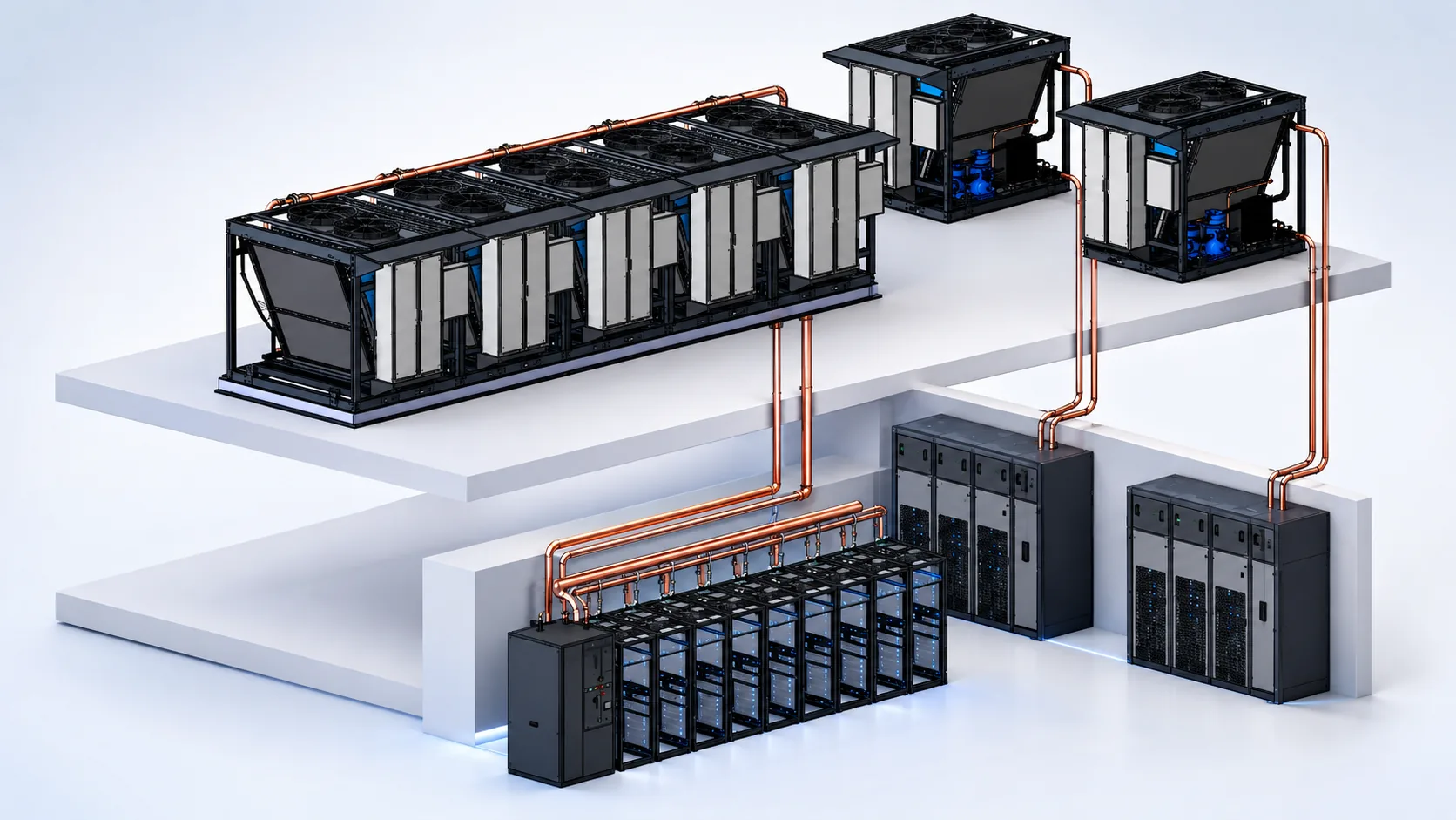
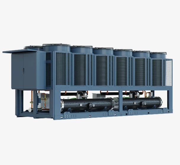
Variable water flow, whether applied to the chilled water circuit, condenser water circuit, or both, is an effective method of reducing pump energy consumption. However, the broader impact on chiller operation must be carefully considered to ensure robust, reliable, and efficient system performance.
In most applications, the actual cooling load experienced by a chiller or chilled water system is often well below the design duty, sometimes significantly so. Chillers respond to these reduced loads by unloading compressors or reducing compressor speed to maintain the required leaving water temperature setpoint. It is therefore logical to reduce the volume of water circulated through the system in line with the cooling demand, thereby achieving additional energy savings through lower pump power consumption.
While this approach offers clear energy-saving benefits, the minimum flow requirements of the chiller and the overall system operating characteristics and design must be carefully evaluated to maintain stable operation and protect equipment performance.
Main Types of Water–Refrigerant Heat Exchangers
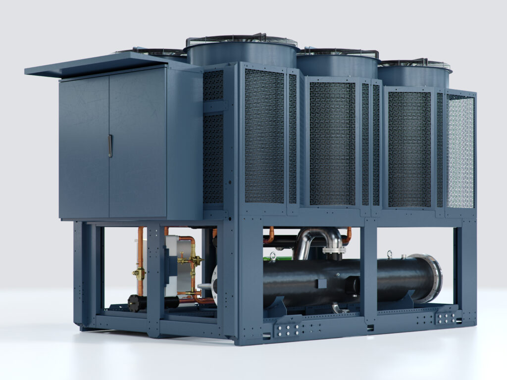
In industrial water chillers, including those used in large-scale data centers, three principal types of water–refrigerant heat exchanger are typically employed:
- Shell-and-Tube Direct Expansion (DX)
- Shell-and-Tube Flooded Refrigerant Heat Exchangers
- Brazed Plate Heat Exchangers
A. Direct Expansion (DX)
In a direct expansion (DX) evaporator, the refrigerant flows and evaporates or condenses within the tubes, while the chilled water passes through the shell side of the heat exchanger. As the refrigerant absorbs heat from the water, it changes phase from a liquid to a vapour, providing the cooling effect required by the system.
Benefits:
- Lower refrigerant charge compared with flooded evaporator designs.
- More compact construction and reduced physical footprint.
- Lower capital cost.
- Simpler refrigerant management and control.
- Good overall efficiency across a wide operating range.
Limitations:
- Lower utilization of the available heat transfer surface compared with flooded evaporators.
- Higher refrigerant superheat requirements, which can reduce overall heat transfer effectiveness.
- Greater sensitivity to refrigerant distribution and load changes.
- Potential susceptibility to tube vibration if flow velocities are not properly controlled.
- Increased risk of localized freezing within the heat exchanger under low-flow or abnormal operating conditions.
- Generally lower peak efficiency than equivalent flooded evaporator designs.
This type of evaporator is commonly used in screw and scroll compressor chillers, where its lower refrigerant charge and compact design offer a cost-effective and reliable solution for commercial and industrial cooling applications.
B. Flooded Refrigerant Heat Exchangers
In a flooded evaporator, the shell contains a reservoir of liquid refrigerant that completely immerses the tube bundle. Chilled water flows through the tubes while the refrigerant on the shell side boils as it absorbs heat from the water. The tubes remain continuously wetted by liquid refrigerant, maximizing the available heat transfer surface area.
Benefits:
- Excellent heat transfer performance due to continuous wetting of the tube surfaces.
- Superior utilization of the heat transfer surface compared with DX evaporators.
- Lower refrigerant superheat requirements.
- Improved chiller efficiency, particularly at full load.
- Lower evaporator approach temperatures, allowing closer temperature differences between refrigerant and water.
- Well suited to large-capacity screw and centrifugal chillers.
- Generally more tolerant of varying load conditions and chilled water temperatures.
Limitations:
- Higher refrigerant charge, resulting in increased refrigerant cost and environmental exposure.
- Larger physical size and weight than equivalent DX evaporators.
- Higher capital cost.
- More complex refrigerant management, including the need for liquid level control systems.
- Additional considerations for oil management and refrigerant distribution, if not paired with an oil-free compressor design.
- Increased maintenance requirements due to the greater complexity of the system.
Flooded evaporators are commonly found in large, water-cooled chillers serving data centers, district cooling networks, hospitals, airports, and other critical cooling applications where maximum efficiency and performance are key design objectives. While they are typically more expensive and complex than DX evaporators, their superior heat transfer characteristics often result in lower operating costs and improved seasonal efficiency over the life of the equipment.
C. Brazed Plate Heat Exchangers
A brazed plate evaporator consists of a series of thin stainless steel plates, vacuum brazed together to form alternating refrigerant and water flow channels. Heat is transferred through the plate surfaces, with the refrigerant evaporating as it absorbs heat from the chilled water circuit.
The corrugated plate design creates high levels of turbulence on both the refrigerant and water sides, resulting in very high heat transfer coefficients and a compact heat exchanger footprint.
Benefits:
- Extremely high heat transfer efficiency due to turbulent flow and large surface area-to-volume ratio.
- Very compact and lightweight compared with shell-and-tube designs.
- Low refrigerant charge.
- Excellent approach temperatures.
- Fast thermal response to load changes.
- Reduced installation space requirements.
- Typically lower material and manufacturing costs for smaller-capacity chillers.
- No tube vibration concerns.
Limitations:
- More sensitive to water quality and fouling due to narrow flow passages.
- Higher pressure drops compared with shell-and-tube heat exchangers.
- Limited ability to mechanically clean internal surfaces.
- Greater susceptibility to blockage from debris or particulate contamination.
- Lower tolerance to freezing conditions; freezing can result in catastrophic plate failure.
- Capacity limitations make them less suitable for very large chillers.
- Repair is generally not practical; replacement is often required if the heat exchanger becomes damaged.
Brazed plate evaporators are widely used in small to medium-capacity chillers employing scroll and screw compressors, particularly where compact dimensions, low refrigerant charge, and high efficiency are key design objectives. They are commonly found in commercial buildings, process cooling applications, heat pumps, and packaged chiller systems.
For larger data center and central plant applications, flooded shell-and-tube evaporators are generally preferred due to their greater robustness, efficiency, serviceability, and tolerance to varying water quality and flow conditions.
Laminar and Chaotic (Turbulent) Flow Through a Chilled Water Heat Exchanger
The way the fluid flows through a heat exchanger is critical to ensuring efficient heat transfer and robust operation. It can be classified into three regimes:
- Laminar flow – smooth, orderly flow with little fluid mixing.
- Transitional flow – an intermediate regime exhibiting characteristics of both laminar and turbulent flow.
- Turbulent flow – chaotic, highly mixed flow that enhances heat transfer.
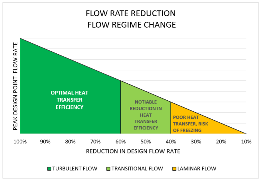
Most refrigerant-to-water heat exchangers are designed to operate in the turbulent flow regime at their design flow rate. Turbulent flow increases fluid mixing at the heat transfer surface, resulting in higher heat transfer coefficients, more uniform fluid temperatures, and greater overall heat exchanger efficiency.
Impacts of Reducing (Variable) Water Flow
As water flow is reduced below the design flow rate, it is important to ensure that the heat exchanger continues to operate within the turbulent flow regime.
Why is this important?
As the water flow rate decreases, the velocity of the water within the heat exchanger tubes also reduces. If the flow rate falls sufficiently, the flow can transition from turbulent to laminar. Under laminar flow conditions, water near the inner tube wall moves very slowly, forming a relatively stagnant layer known as the boundary layer.
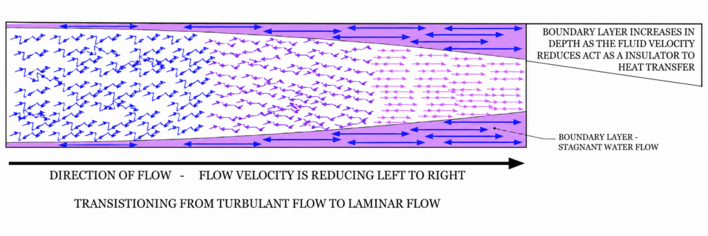
As the flow rate decreases, this boundary layer becomes progressively thicker. The boundary layer acts as an insulating barrier between the bulk water flowing through the tube and the tube wall, reducing the rate of heat transfer to the refrigerant on the opposite side of the heat exchanger surface.
The consequences of excessive boundary layer formation can include:
- Reduced heat transfer efficiency.
- Higher evaporator approach temperatures.
- Reduced chiller capacity and performance.
- Poorer leaving water temperature control.
- Increased risk of localized freezing within the evaporator.
- Potential chiller alarms, trips, or operational instability.
For these reasons, variable-flow chilled water systems must be designed and controlled to maintain the minimum water velocity and flow rate specified by the chiller manufacturer. This ensures that turbulent flow is maintained, maximizing heat transfer performance while allowing the energy-saving benefits of variable-speed pumping to be realized.
Most chiller evaporators are designed to maintain turbulent water flow between 100% and approximately 60% of their design flow rate, while keeping water-side pressure drop and tube velocities within acceptable limits. Below this range, the risk of transitioning into the laminar flow regime increases, leading to reduced heat transfer efficiency, degraded chiller performance, and potentially even causing catastrophic damage.
Variable Flow Considerations
It is not uncommon to see chilled water specifications requiring a chiller to operate over a variable flow range of 50% (or less) to 100% of design flow. However, reducing evaporator flow rates significantly below approximately 60% of design flow is often not conducive to robust and reliable chiller operation for several reasons:
1. Increased Risk of Laminar Flow
As flow rates reduce, the water velocity within the evaporator tubes decreases. Below a certain threshold, the flow may transition from turbulent to laminar, resulting in a thicker boundary layer forming on the tube walls. This insulating layer reduces heat transfer performance, increases evaporator approach temperatures, and can adversely affect chiller efficiency and stability.
2. Higher Pressure Drops in Optimized Variable-Flow Designs
If turbulent flow is to be maintained at very low flow rates, the evaporator must typically be designed with smaller flow passages and higher design water velocities. While this can extend the turbulent operating range, it also results in significantly higher water-side pressure drops through the heat exchanger. Consequently, additional pump head and pump power are required, offsetting some of the energy-saving benefits of variable flow operation and leading to a less optimized overall system design.
3. Excessive Chiller Operation at Part Load
Very low system flow rates are often associated with reduced cooling loads. In many cases, operating a large number of chillers at low load is less efficient than reducing the number of chillers online and increasing the loading of the remaining units. Optimizing chiller sequencing can improve plant efficiency, reduce total pump power consumption, and enhance overall system reliability by operating fewer chillers closer to their optimum performance point.
Design Considerations
Rather than specifying an extremely wide chiller flow range, designers should evaluate the interaction between evaporator performance, pump energy, pressure drop, and chiller sequencing. In many applications, maintaining evaporator flow rates above approximately 60% of design flow while staging chillers appropriately will deliver a better balance of efficiency, reliability, and operational robustness than attempting to achieve very low flow operation through a greater number of chillers.
Future Developments
Flooded evaporators are widely regarded as the most thermally efficient solution for chiller applications, but their main disadvantage is the large refrigerant charge required. This increases both system cost and the potential environmental impact of refrigerant leaks should they occur.
A technology that can deliver similar efficiency with a much lower refrigerant charge is the falling film evaporator, which has been successfully used in other industries for many years. In this design, liquid refrigerant is distributed over the top of a vertically mounted heat exchanger and flows downward under gravity as a thin film over the tube surfaces. Because only a thin refrigerant layer is needed, the total refrigerant charge is significantly lower than in a flooded evaporator.
However, applying falling film technology to liquid chillers in environments such as data centers and commercial cooling presents challenges. The heat exchanger should ideally be mounted vertically, which can conflict with the transport and dimensional requirements of industrial and commercial chillers that typically use horizontal evaporators. In addition, efficient operation requires a minimum refrigerant flow rate to maintain complete tube wetting. At part load, reduced refrigerant flow can cause dry areas on the tubes, lowering heat transfer performance and making refrigerant control more difficult.
While falling film evaporators offer the potential to combine the efficiency of flooded systems with a substantially lower refrigerant charge, further development is needed to overcome challenges related to system layout, refrigerant distribution, and stable operation across the wide load range typical of most chiller applications.
Variable Flow in Conclusion
Variable water flow through chilled water systems and chiller evaporators is a simple and effective method of reducing pump energy consumption and improving overall system efficiency. However, it must be applied within defined operating limits to maintain adequate heat transfer, stable control, and reliable chiller operation through a plant’s overall lifecycle. When properly designed and controlled, variable flow systems can deliver significant energy savings while ensuring long-term equipment reliability, plant longevity, and optimum performance.
Maximizing efficiency isn't just about turning down pump speeds – it requires evaluating the complex trade-offs between heat exchanger fluid dynamics, pressure drops, and chiller sequencing to ensure long-term operational robustness.

Want to explore these cooling topics with your team?
Our CIBSE-approved Data Center Cooling CPD gives consultants and engineers the opportunity to discuss cooling principles, trade-offs and project-relevant questions directly with Munters specialists. Explore the CPD →