

Noise is a form of energy; while it cannot be eliminated (as much as we would like to), it can be effectively controlled and reduced.
Noise control is a complex subject, and there are many specialists with far deeper expertise than myself. However, the purpose of this document is not to provide an exhaustive technical analysis. Instead, it aims to explain key principles in a clear and practical way, offer a basic understanding of how noise behaves, and outline effective methods for reducing noise –particularly in relation to chillers.
Noise exists in many different forms, and to describe it accurately, we typically consider two key parameters:
- Character – defined by its frequency, measured in Hertz (Hz).
- Magnitude – defined by its strength or intensity, measured in decibels (dB).
Frequency Hz
There is a theoretically infinite range of possible frequencies. However, to ensure consistency and allow meaningful comparison between different machines, noise is typically analysed and reported using standard frequency bands. These are commonly referred to as octave bands (or sometimes third-octave bands), which group frequencies into defined ranges and provide a consistent basis for measurement and comparison.
| STANDARD OCTAVE FREQUENCY BANDS Hz | |||||||
| 63 | 125 | 250 | 500 | 1000 | 2000 | 4000 | 8000 |
Decibels dB
The strength of noise within each frequency band is expressed in decibels (dB). As sound travels away from its source, its strength decreases with distance. In simple terms, this relationship follows the inverse square law, meaning that the sound level at a given point is inversely proportional to the square of the distance from the source. As a rule of thumb, sound levels decrease by approximately 6 dB for every doubling of distance from the source, assuming free-field conditions.
The human ear perceives sound on a logarithmic scale, meaning equal ratios of sound energy are perceived as similar changes in loudness. For example, an increase in sound power from 0.1 W to 1 W, 1 W to 10 W, or 10 W to 100 W represents the same tenfold increase and is perceived as a similar step in loudness.
To reflect this behaviour, sound levels are expressed in decibels (dB), which are a logarithmic unit.
It is important to note that the decibel is a relative unit, not an absolute measure. In acoustics, sound levels are typically referenced to a standard intensity of 10⁻¹² watts per square metre (W/m²), which corresponds approximately to the threshold of human hearing.
Basic Terminology
Noise is a form of energy. According to the principle of conservation of energy, it cannot be created or destroyed, only converted from one form to another. In mechanical systems, such as a motor driving a fan, energy is primarily converted into motion and airflow. However, a small proportion of this energy is also converted into acoustic energy, which we perceive as noise.
Sound Power (SWL)
This describes the sound power level at the source (e.g. a compressor or fan). It cannot be measured directly but is derived by back-calculating from measured sound pressure levels. The unit used is decibels (dB).
Sound Pressure (SPL)
This is the strength of sound at a given distance from the source, it is the only value that can be measured because the sound measuring instrument will always be at a distance from the source, no matter how small, again its value is decibels dB at (X) distance from the source.
To illustrate this concept, a useful analogy is a convection heater. The heater consumes power at the source and emits thermal energy. At a distance, the amount of energy perceived is reduced due to dispersion. Similarly, a noise source emits sound power, which propagates through space, and the sound pressure level measured at a given location represents the energy perceived at that point.
Breakout Noise
Breakout noise is the sound radiated from the external surfaces of equipment or enclosures into the surrounding space. It is quantified as a sound power level and is used by acoustic engineers to evaluate the total noise emission of a plant item, considering both its surface area and the efficiency of sound radiation.
Free Field Conditions
This describes the conditions under which noise emitted from a source has been measured. Free field noise is expressed as the Sound Pressure Level (SPL) across specified frequency bands, measured at a defined distance and elevation from the source. These measurements are taken under free field conditions, meaning there are no reflecting surfaces influencing the sound propagation.
This method is typically used for equipment intended for outdoor installation, where sound radiates unobstructed into the surrounding environment.
Hemispherical and Semi-Hemispherical Noise Transmission
Sound pressure levels are often quoted based on hemispherical or semi-hemispherical sound radiation conditions, which describe how sound propagates from a source in relation to surrounding surfaces.
- Hemispherical radiation assumes the equipment is radiating sound into a free field above a single reflecting plane (typically the ground). This represents a source positioned outdoors, where sound spreads over a hemisphere.
- Semi-hemispherical radiation assumes additional reflecting surfaces are present (such as walls or corners), effectively restricting the sound radiation to a smaller space and increasing measured sound pressure levels due to reflections.
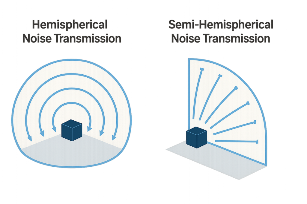
In simple terms, the more reflective boundaries surrounding a source, the less the sound energy can disperse, resulting in higher measured sound pressure levels at a given distance.
Comparing Noice Levels db(A)
In order to make meaningful comparisons between equipment from different manufacturers, it is essential to ensure that measurements are presented on a consistent basis. To achieve this, the industry commonly uses A-weighted decibel values (dB(A)).
The dB(A) scale applies a frequency weighting that reflects the sensitivity of the human ear, which does not perceive all frequencies equally. Lower and very high frequencies are less readily perceived than mid-range frequencies, and the A-weighting adjusts the measured sound levels accordingly.
For example, a sound level of 70 dB at 63 Hz is perceived by the human ear as having a similar loudness to approximately 44 dB at 1 kHz.
By using dB(A) weighting, the relative impact of different frequencies is accounted for, allowing for a more accurate representation of how noise is experienced by people. This enables fair and practical comparisons of noise emissions across different equipment.
| ‘A’ Weighted Adjustment to SPL dB Levels | ||||||||
| 63 | 125 | 250 | 500 | 1000 | 2000 | 4000 | 8000 | Hz |
| -26 | -16 | -9 | -3 | 0 | +1 | +1 | -1 | dB |
How do you get to a single dB(A) figure?
Take your measured sound spectrum for an item of equipment and apply the ‘A’ weighted adjustments.
| ‘A’ Weighted Adjustment to SPL dB Levels | ||||||||
| 63 | 125 | 250 | 500 | 1000 | 2000 | 4000 | 8000 | Hz |
| 50 | 51 | 51 | 55 | 54 | 49 | 44 | 50 | dB @ 10m |
| -26 | -16 | -9 | -3 | 0 | +1 | +1 | -1 | dB |
| 24 | 35 | 42 | 52 | 54 | 50 | 45 | 39 | dB(A) |
Then take the new values across the spectrum and pair them together from the lowest to the highest frequencies, you then take the larger of the two numbers and add the following correction value based how much the differ from each other.
| Frequency Pair Adjustments | |
| Difference between dB values | Add (dB) |
| 0 or 1 | 3 |
| 2 or 3 | 2 |
| 4 to 9 | 1 |
| >10 | 0 |
Example
| Taking ‘A’ weighted adjustment to A Single dB(A) Value @ 10m distance | ||||||||
| 63 | 125 | 250 | 500 | 1000 | 2000 | 4000 | 8000 | Hz |
| 24 | 35 | 42 | 52 | 54 | 50 | 45 | 39 | dB(A) |
| 24 ≠ 35 =11 ADD 0 | ||||||||
| 35 | ||||||||
| 42 ≠ 35 = 7 = ADD 1 | ||||||||
| 43 | ||||||||
| Diff 52 ≠ 43 = 9 = ADD 1 | ||||||||
| 53 | ||||||||
| Diff 53 ≠ 54 = 1 = ADD 3 | ||||||||
| 56 | ||||||||
| Diff 56 ≠ 50 = 6 = ADD 1 | ||||||||
| 57 | ||||||||
| Diff 57 ≠ 45 = 12 = ADD 0 | ||||||||
| 57 | ||||||||
| Diff 57 ≠ 39 = 18 = ADD 0 | ||||||||
| Final overall single value = 57 | dB(A) | |||||||
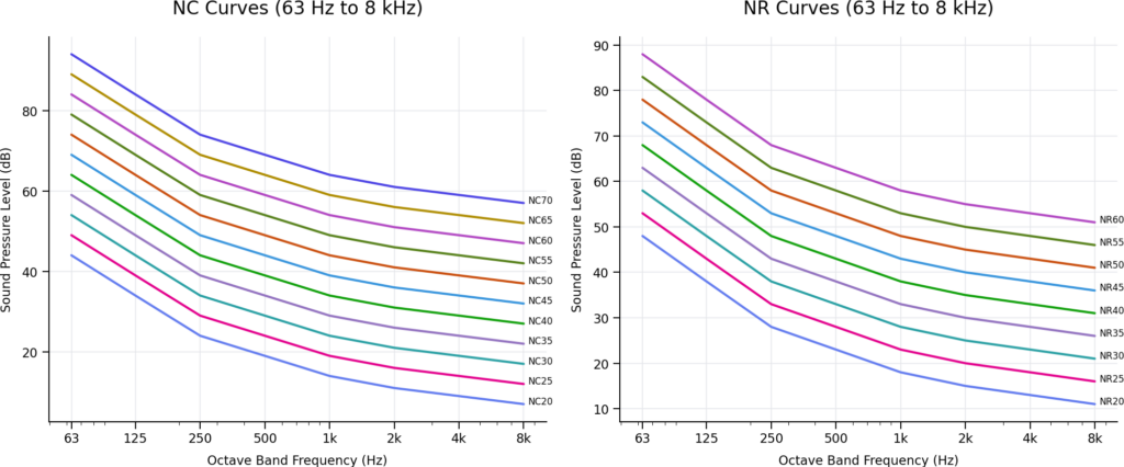
NC / NR Noise Criteria
The Noise Criteria (NC) and Noise Rating (NR) systems were developed in the United States and Europe respectively. Both systems consist of a family of curves plotted across octave frequency bands, representing acceptable noise levels in relation to human perception.
To determine the NC or NR rating of a noise source, the measured Sound Pressure Level (SPL) values for each frequency band are plotted onto the corresponding NC or NR chart. The rating is then defined by the highest curve that is touched or exceeded by any part of the noise spectrum.
The resulting NC or NR value is a single-number rating used to describe the overall noise characteristic. It is important to note that this value is dimensionless (i.e., it has no units).
These systems are widely used in building services and HVAC applications to assess noise acceptability in occupied spaces.
Useful rules of thumb:
To adjust sound levels (dB) over distance, the table below can be applied to each frequency band. Alternatively, as a general guide, doubling the distance from the source results in a reduction of approximately 6 dB.
| Distance Correction Factor | |
| Distance from source | dB Reduction |
| 0 | 0 |
| 1 | 8 |
| 2 | 14 |
| 3 | 18 |
| 4 | 20 |
| 5 | 22 |
| 10 | 28 |
| 20 | 34 |
Two identical noise sources will increase the overall sound level by approximately 3 dB when combined.
In general, the increase in sound level from multiple identical sources follows a base‑10 logarithmic relationship. The examples below show rounded values for 2 to 8 identical sources.
| Number of Identical Sources Correction Factor | |
| Number | dB Increase |
| 2 | 3 |
| 3 | 5 |
| 4 | 6 |
| 6 | 8 |
| 8 | 9 |
Now that we have a better understanding of noise, what can we do to control its emission from chillers?
This document focuses solely on chiller design in relation to sound. The broader topic of full external acoustic attenuation is a separate and more extensive subject, which I hope to discuss in a future document.
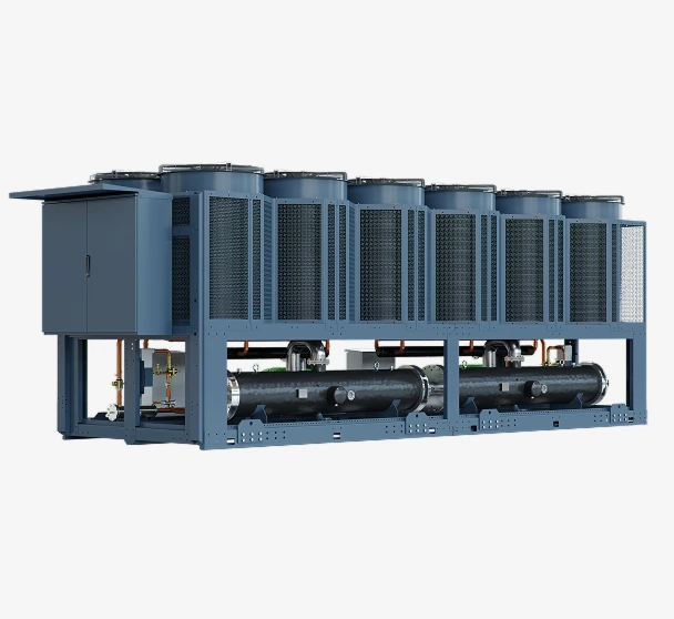
There are three primary sources of noise within a chiller:
- Compressors
- Pumps (when integrated into the chiller)
- Fans (particularly in air-cooled chillers)
The first two sources, compressors and pumps are relatively straightforward to manage. They can be enclosed within acoustic housings lined with sound-absorbing materials to reduce noise emissions. However, a critical factor must be considered: heat dissipation.
If a compressor or pump is completely sealed within an enclosure, noise transmission can be significantly reduced, but at the expense of airflow. This restricts the removal of heat generated during operation, potentially leading to overheating and premature component failure.
Therefore, when designing these enclosures, manufacturers must strike a balance between noise attenuation and effective ventilation. A common solution is to incorporate ventilation fans within the enclosure to promote airflow. The air inlets and outlets are then acoustically treated using attenuators, baffles, or lined ductwork to minimise the noise that can escape through these openings.
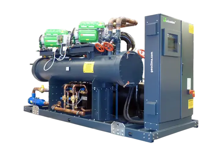
Noise Benefits of Turbocor compressors
Munters’ use of Turbocor oil-free compressors provides a significant advantage over alternative compressor technologies, such as screw compressors, particularly in terms of noise performance. Turbocor compressors typically operate within the 70–78 dB(A) range, whereas screw compressors generally operate between 80–95 dB(A) measured at 1 metre. This represents a reduction of up to 15 dB(A), a substantial difference in perceived loudness—even before the application of any acoustic enclosures or attenuation measures.
In addition to lower overall sound levels, Turbocor and screw compressors differ significantly in their sound characteristics. Turbocor compressors are dominated by higher-frequency noise, while screw compressors tend to produce more energy in the low- to mid-frequency ranges. This distinction is important, as higher-frequency noise is generally easier to attenuate using conventional acoustic treatments, whereas low-frequency noise is more difficult to control and can travel further.
A further benefit of Turbocor technology is its inherently low vibration levels, due to the use of magnetic bearings and the absence of mechanical contact. This not only reduces structure-borne noise transmission but also simplifies acoustic isolation. Combined with the more favourable frequency profile, this makes Turbocor-based systems significantly easier to manage in noise-sensitive applications.
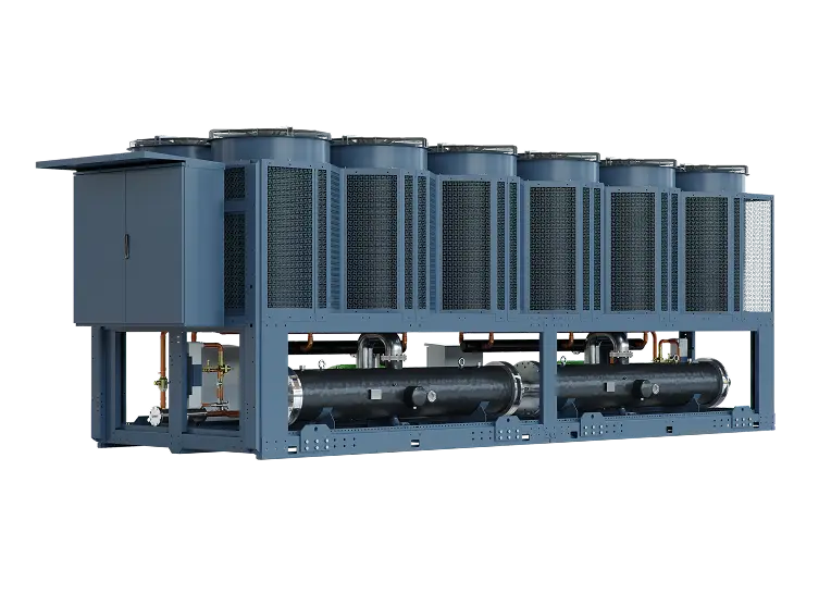
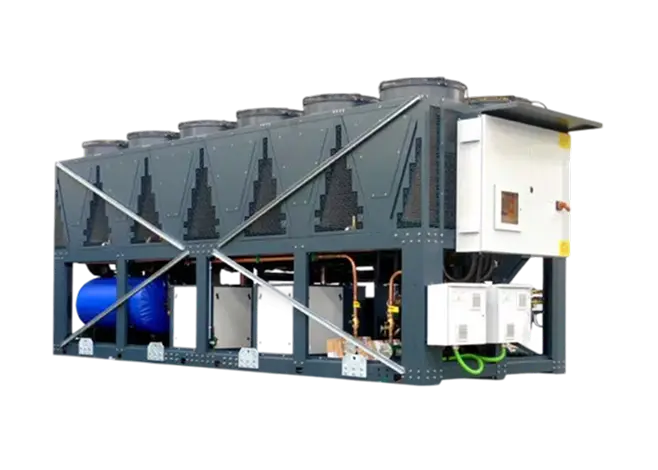
Fan and Airflow Noise Mitigation in Air-Cooled Chillers
Fan and airflow noise represent a significant component of overall chiller acoustic emissions and are inherently more complex to control due to their strong dependence on aerodynamic behaviour. However, a range of engineering strategies can be employed to achieve measurable noise reductions while balancing thermodynamic and energy performance.
1. Reduction of Fan Tip Speed and Optimisation of Fan Diameter
A primary method of reducing aerodynamic noise is to lower fan rotational speed (and therefore tip speed), while increasing fan diameter where spatial constraints permit. This enables the required volumetric airflow to be maintained at reduced acoustic output.
In practice, reductions in fan speed must often be accompanied by an increase in condenser heat exchange surface area to maintain thermal performance, which can result in a larger chiller footprint unless advanced technologies like Munters Circlemiser® Circular coil technology is employed.
It is important to recognise the thermodynamic trade-off associated with this approach. Lower airflow rates may elevate condensing temperatures and pressures, increase compressor lift and potentially leading to higher electrical energy consumption if not carefully engineered.
When appropriately balanced with condenser sizing, reductions in fan speed can typically yield noise reductions in the order of 3–6 dB, with higher reductions achievable in optimised designs.
2. Advanced Fan Blade Geometry
Ongoing developments in fan blade design have resulted in measurable improvements in both aerodynamic efficiency and acoustic performance. Modern blade profiles such as aerofoil sections or sickle-shaped geometries are designed to minimise flow separation and reduce vortex formation.
Additionally, the incorporation of trailing-edge serrations can disrupt coherent vortex shedding, thereby reducing broadband noise emissions. These features collectively contribute to lower sound power levels while maintaining or improving airflow performance and electrical efficiency.

3. Electronically Commutated (EC) Fan Motors
Electronically commutated (EC) motors offer superior efficiency and control compared to conventional AC motor technologies. While the direct acoustic benefit of the motor itself is modest, the principal advantage lies in the ability to achieve continuous, precise speed modulation.
This enables operation at reduced fan speeds for a significant proportion of the annual operating profile, particularly during part-load and low ambient conditions. As aerodynamic noise is strongly dependent on fan speed, this results in concurrent reductions in both sound emissions and energy consumption.
4. Dynamic Noise Control®

Dynamic Noise Control® developed by Munters utilise real-time acoustic monitoring to actively manage chiller sound output in relation to predefined operational limits, such as those imposed by planning or environmental regulations.
These systems employ strategically positioned microphones within the chiller frame to measure sound levels and dynamically adjust system operation in response. Control strategies may include:
- Reducing fan speed, with a corresponding increase in condensing pressure, or
- During lower ambient temperatures (e.g. night-time operation), unloading compressors to reduce overall system noise
When properly configured and integrated within the initial equipment selection process, such systems can provide a high degree of assurance that site-specific noise constraints are consistently met.
5. Fan Discharge Attenuation and Flow Management
The use of discharge attenuators, acoustic pods, or cowlings provides multiple complementary benefits:
- Acoustic attenuation: The inclusion of sound-absorbing materials reduces radiated noise, particularly in lateral directions.
- Airflow optimisation: Straightening of the discharge airflow reduces turbulence and swirl losses, improving fan efficiency and enabling operation at lower speeds.
- Reduction of air recirculation: By directing exhaust air further from the condenser intake, the likelihood of hot air recirculation is diminished. This lowers entering air temperature at the coil, improving heat rejection performance, reducing condensing pressure, and potentially lowering compressor energy consumption.
6. Inlet Bellmouth Design
When increased chiller height permits, Bellmouth inlets can be employed at the fan intake to improve aerodynamic entry conditions. By smoothing the transition of air into the fan, these devices reduce inlet losses and minimise turbulence.
This results in lower noise generation due to reduced flow separation and velocity fluctuations, while simultaneously enhancing fan efficiency. In optimised systems, these improvements may allow for marginal reductions in fan rotational speed without compromising airflow performance.
Fan and Airflow Conclusions
Effective control of fan and airflow noise in air-cooled chillers requires a holistic engineering approach that considers aerodynamic, thermodynamic, and acoustic interactions. While individual measures can deliver meaningful noise reductions, the greatest benefits are achieved through integrated system design, where fan selection, heat exchanger sizing, control strategy, and acoustic treatment are optimised collectively.
Careful balancing of noise reduction techniques with system efficiency is essential to avoid unintended increases in energy consumption, ensuring that both acoustic and environmental performance objectives are met.
Additional Considerations in Modern Low-Noise Chiller Design
Advancements in compressor technology, particularly the adoption of oil-free magnetic bearing centrifugal compressors such as Turbocor®, have significantly reduced overall chiller noise levels. As a result, previously negligible noise sources have become more perceptible, necessitating additional design considerations.
Refrigerant Flow-Induced Noise
One such emerging noise source is the high-velocity refrigerant flow within pipework. Historically, this form of noise was masked by the relatively high sound levels generated by traditional compressor technologies. However, with the substantially lower acoustic signature of modern compressors, flow-induced noise—particularly in discharge lines—can now be distinguished and may contribute meaningfully to overall system sound emissions.
This noise arises primarily from turbulent flow, pressure fluctuations, and interaction between the refrigerant and pipe walls, particularly at high velocities or in areas of flow disturbance such as bends, valves, and transitions.
To address this, Munters has developed acoustically treated pipework insulation systems. These solutions incorporate multilayer materials designed not only for thermal insulation but also for acoustic absorption and damping, reducing the transmission of structure borne and airborne noise from refrigerant flow.
Compressor Discharge Noise Mitigation – Turbocor®
The refrigerant discharge line is typically the most significant source of flow-induced noise due to elevated pressure, and velocity conditions at the compressor outlet. In response, Turbocor® has developed a “Discharge resonator”, which is integrated directly at the compressor discharge connection.
This device operates as a passive acoustic attenuation system, designed to target specific frequencies associated with discharge gas pulsations and flow noise. The resonator is tuned to generate pressure oscillations that are out of phase with the dominant noise frequencies produced by the refrigerant flow. Through the principle of destructive interference, this results in a reduction in the perceived sound level.
This mechanism is analogous to active noise cancelling technologies in concept; however, it is entirely passive in operation, requiring no external energy input or control system. The result is a robust and reliable reduction in tonal and broadband noise components associated with discharge flow, contributing to the overall low-noise performance of the chiller.
In conclusion
The control of noise emissions from chillers—particularly air-cooled systems—can present significant engineering challenges due to the complex interaction of aerodynamic, mechanical, and thermodynamic factors. However, through the application of advanced chiller design principles, combined with the expertise of Munters’ application engineering teams, it is consistently possible to develop solutions that are technically robust, practically achievable, and acoustically effective. These solutions leverage innovative technologies and system-level optimisation to ensure compliance with increasingly stringent noise requirements while maintaining overall performance and efficiency.
The most effective way to reduce chiller noise is to design for it from the start – balancing acoustic performance with airflow, efficiency and long-term system reliability.